Updates
2022-12-1: Replaced OLED by LCD in two places (See Thanks)
What’s there
The board
Here is what you have on those boards:
- Two 2x5 pins connectors (EXP1 and EXP2), conveniently non-separated as you need both to use the screen.
- Rotary encoder with detent and pushable. Feels nice and sturdy
- 1 Push button (used for reset)
- 3 Neopixels (WS2811) for the background lights. 2 for the rotary encoder 1 for the LCD screen (uses a lightguide and it makes a pretty homogeneous backlight)
- 1 LCD screen monochrome 128x64 pixels with some kind of ST7567 JLX12864 interface.
- 1 buzzer
- 1 SDcard port (I’ve not tested it yet)
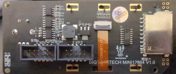
That’s what the back of the device looks like:

The black rounded square is the buzzer, the chips on the left are the WS2811 for the RGB leds, the long chip on the right is a level-shifter for 5 to 3V3. The three-legged one is a voltage regulator to make the 3V3. And the tiny transistor next to the buzzer is to control it. A NPN J3Y with a 330 ohms resistor on the base.
Note: These tiny boards, despite being named V1.0, have a neopixel backlight system. For other brands, it is the version 2.1 that uses those neopixels, the previous ones have standard single color or rgb.
I had to use a few resources I listed at the end of this article. The naming of the pins is extremely confusing between devices and libraries. And every little board like these like to do things slightly differently. That’s why I gave (way too many) details so you can figure out what’s different with yours.
The pins

EXP1 seen from the board, notch at the top as on the picture above
| ———- | ———- | __________ | ———- | ———- |
|---|---|---|---|---|
| GND | NC? | LCD reset | LCD CS | Beeper |
| 5V | NC? | Neopixel data | LCD RS | Encoder button |
EXP2 seen from the board, notch at the top as on the picture above
| ———- | ———- | __________ | ———- | ———- |
|---|---|---|---|---|
| GND | SD Detect | Encoder B | Encoder A | MISO (SD) |
| NC? | Push button | MOSI (common) | SD CS/SS | Clock (common) |
How does this all work
Now, compared to older controllers for repraps. Here some of the clock and data lines are shared between the screen and the sd card.
The board generates the necessary 3V3 with its own 1117-3.3 and has a 74HC4050D non-inverting level shifter (not that it matters much). Looks like the SDCard has its MISO connected directly to EXP2, so it is a 3V3 on a connector where everything else is 5V.
Push button
The push button is pulled up to 5V with a 10K resistor.
Non populated headers
There are non populated headers on the side of the board, they are connected to the card detect, MISO, MOSI, SS, SCK and 3V3/Gnd of the SDcard.
Neopixel
The 3 neopixels chips (WS2811 solo chips, they are not those all-in-one kind) are connected in sequence. They use a totally normal protocol, it looks like we don’t have a way to get the DOUT of the last pixel, so either you will have to solder a wire there or use the screen as the last 3 leds.
The first 2 pixels are used for the encoder (one per side) the third one is for the backlight of the screen (and you’d better use it). The color order is Green, Red, Blue.
This is what I used. Note that the encoder ones are really bright, so I had to tone them down.
#include <Adafruit_NeoPixel.h>
#ifdef __AVR__
#include <avr/power.h>
#endif

#define NEOPIXEL_PIN 3

Adafruit_NeoPixel strip = Adafruit_NeoPixel(3, NEOPIXEL_PIN, NEO_GRB);

strip.begin();
strip.setBrightness(255);
strip.setPixelColor(0, strip.Color(25, 25, 25));
strip.setPixelColor(1, strip.Color(25, 25, 25));
strip.setPixelColor(2, strip.Color(255, 255, 255));
strip.show();
LCD screen
Careful, you need to use the Neopixels (at least the third one) to get the backlight of the screen.
This is what you need to connect the LCD:
- LCD Reset
- LCD CS
- LCD RS
- MOSI
- Clock (Common)
- 5V
- GND
And this is how you use it with U8G2:
#include <U8g2lib.h>

// obviously replace that by the pins you are using
#define LCD_CLOCK 10  // Clock (Common), sometimes called SCK or SCL
#define LCD_MOSI 11   // MOSI (common), sometimes called SDA or DATA
#define LCD_RESET 7   // LCD reset, sometimes called RST or RSTB
#define LCD_CS 9      // LCD CS, sometimes called EN or SS
#deinfe LCD_RS 8      // LCD RS, sometimes called A0 or DC

U8G2_ST7567_JLX12864_1_4W_SW_SPI u8g2_lcd(U8G2_R0,
                                          LCD_CLOCK,
                                          LCD_MOSI,
                                          LCD_CS,
                                          LCD_RS,
                                          LCD_RESET); // clock, data, cs, dc, reset
void display_on_lcd() {
    u8g2_lcd.begin();
    u8g2_lcd.setContrast(180);  // This is extremely important
    u8g2_lcd.clearBuffer();
    u8g2_lcd.firstPage();
    do {
        u8g2_lcd.setFont(u8g2_font_6x12_tr);
        u8g2_lcd.setFontMode(0);
        u8g2_lcd.drawHLine(0, 58, 128);
        u8g2_lcd.drawStr(10, 10, "HELLO");
    } while ( u8g2_lcd.nextPage() );
}
Encoder
The encoder seems to make 4 pulses per direction and is a 90 degrees phase encoded on its two pins. All the inputs are put to GND in the encoder, so you have to use pull ups.
To use it (and the screen) with ArduinoMenu:
// Here I'm assuming you already have a MENU, if not, just look at the ArduinoMenu examples


#include <menu.h>
#include <menuIO/u8g2Out.h>
#include <menuIO/clickEncoderIn.h>
#include <TimerOne.h>
#include <U8g2lib.h>

#define PULSES_PER_STEP 4

ClickEncoder clickEncoder(BTN_UP, BTN_DOWN, BTN_SEL, PULSES_PER_STEP);
ClickEncoderStream encStream(clickEncoder,1);
void timerIsr() {clickEncoder.service();}


const colorDef<uint8_t> colors[6] MEMMODE={
        {{0,0},{0,1,1}},//bgColor
        {{1,1},{1,0,0}},//fgColor
        {{1,1},{1,0,0}},//valColor
        {{1,1},{1,0,0}},//unitColor
        {{0,1},{0,0,1}},//cursorColor
        {{1,1},{1,0,0}},//titleColor
};


#define fontX 7
#define fontY 12
#define offsetX 0
#define offsetY 2
#define U8_Width 128
#define U8_Height 64


MENU_OUTPUTS(out,MAX_DEPTH
,U8G2_OUT(u8g2_lcd,colors,fontX,fontY,offsetX,offsetY,{0,0,U8_Width/fontX,U8_Height/fontY})
,NONE
);


NAVROOT(nav,mainMenu,MAX_DEPTH, encStream, out);

void setup() {
    Timer1.initialize(1000);
    Timer1.attachInterrupt(timerIsr);
}
Buzzer
I did put it on the Pin 13 of my Arduino Mega, that way it makes weird sounds whenever the program uploads or when the arduino boots because that’s the pin of the L Led.
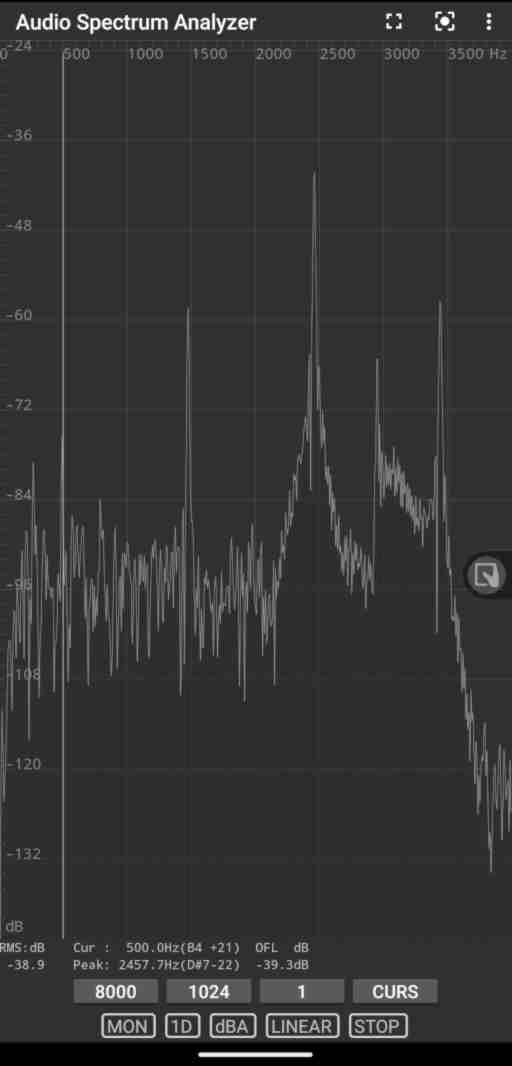
// This will make a roughly 200ms nicely squarish 500Hz-ish beep
for (int i=0;i<100;i++) {
        digitalWrite(13,0);
        delay(1);
        digitalWrite(13,255);
        delay(1);
}
Conclusion
That’s a nice and easy to use device, it is really well constructed and inexpensive. Totally recommend it if you need to add a human interface to your projects.
I may revisit this article at some point to add info about the SDcard if there is anything special.
Resources
- Pinouts: https://github.com/bigtreetech/BGTHREETECH-MINI-12864-V1.0/blob/master/Hardware/BIGTREETECH%20MINI12864%20Interface.pdf
- Schematics (from another brand so careful): https://github.com/FYSETC/FYSETC-Mini-12864-Panel/blob/master/hardware/V2.1/Mini12864%EF%BC%88RGB%EF%BC%89V2.1_sch.pdf
- Interfacing with U8G2 (in German): https://github.com/olikraus/u8g2/issues/1608
- U8G2 library: https://github.com/olikraus/u8g2
- Arduino Menu: https://github.com/neu-rah/ArduinoMenu
- Timer One: https://github.com/PaulStoffregen/TimerOne
- Adafruit neopixel: https://github.com/adafruit/Adafruit_NeoPixel
Thanks
Jenny List for listing on the hackaday blog and Björn Andersson for the constructive comment (that’s a LCD not a OLED screen indeed).